The
visual appearance of the surface of an object depends on the way the
light energy that is incident on the surface interacts with the
material. Light is a form of electromagnetic energy, the same
form of energy as television or radio signals.
Electromagnetic
energy has the form of an oscillating magnetic and electric wave that
travels in straight lines at speeds of order 286,000 miles per
second. The frequency of oscillation determines the
wavelength of
the radiation, the higher the frequency of oscillation then the shorter
the wavelength.
Light
is the term used for radiation in the band of wavelengths that are
visible to the human eye. Each wavelength in the visible
range
triggers a different response from the receptors in the eye and appears
to have a different colour. White is the sensation given by
light
that contains a blend of wavelengths from all parts of the visible
spectrum. Isaac Newton in Cambridge in 1666 was the first to
show
that white sunlight is a combination of light of all the basic colours.
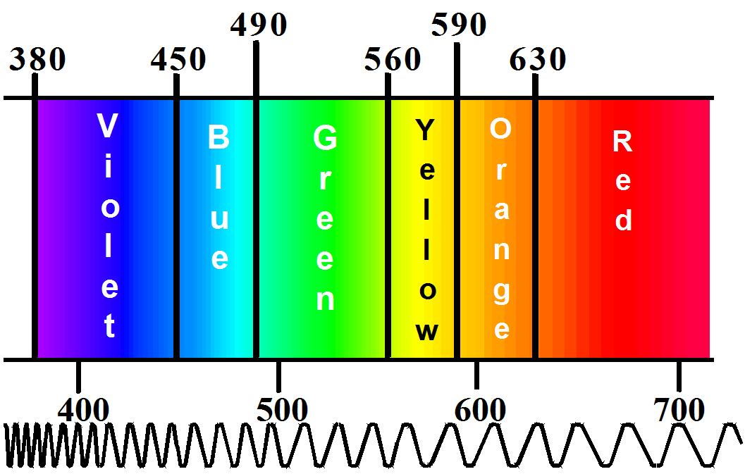
The
human eye responds to electromagnetic radiation over a very limited
range of wavelengths. The range, for a person with normal colour
vision, is from 380nm to 730nm, where nm stands for nanometre and is a
thousand millionth of a metre (10-9m).
For most practical purposes the range of sensitivity of the eye can be
taken as from 400nm to 700nm, as illustrated in Figure 1. The
associations between the wavelength bands and the colour names are only
approximate since the colours merge smoothly from one band to another.
The
light that is entering the eye gives rise to the sensation of
colour. The sensation of colour is the interpretation by the
brain of the signals coming from the eyes.
Some
materials appear coloured because they create light by the conversion
of energy in another form into light. These materials are classed as
"self luminous", a colour television screen and the lamps in the room
are examples of this type, and both convert electrical energy into
light.
Figure1: Colour names against wavelength (nm).
It
is clear, just by looking around, that the majority of coloured objects
can be classed as "reflective" or "surface colours". They
appear
coloured because of the interaction of the light shining onto their
surfaces with the atoms and molecules within the surface
region.
The majority of materials produced by the coating industry are surface
colours.
Colour
by reflection
The
selective absorption of wavelengths from white light is probably the
most common way of creating colour. The white light shone
onto a
plain white surface is reflected evenly across the spectrum to cause a
balanced set of visual signals to be passed from the eye to the
brain. This is interpreted as "White".
In
a coloured material, the pigments or dyes that are present absorb some
of the wavelengths from the incident light, often converting the
absorbed light into heat energy. The remaining wavelengths
are
reflected back by the background or by any highly scattering "white"
pigments that may be present.
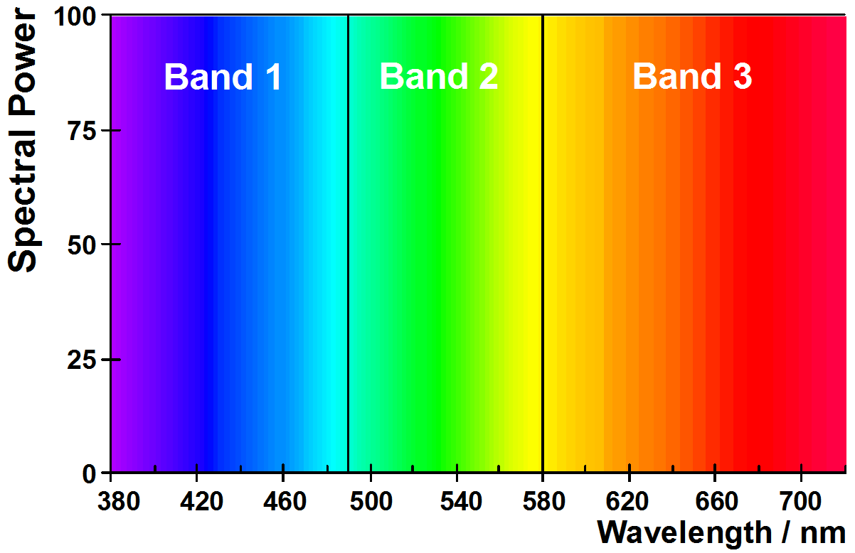
To
appear coloured, a material should absorb light from wavelengths within
one, or at most two of the bands shown in Figure 2. If the
material does not absorb light in any of the bands then it will appear
white. If it absorbs wavelengths spread evenly through all three of the
bands then it will appear grey or black.
A
red object appears red because the light with wavelengths in the blue
band (1) and green band (2) are absorbed by the material and only the
wavelengths in the red band (3) are reflected into the eye.
Figure2: A coloured material will absorb light from
one, or at most two wavelength bands.
Table 1
shows the reflected colour observed for each combination of band
absorbed or reflected.
Table1:
The band of light that is absorbed or reflected and the associated
surface colour.
Colour
Band 1
Band 2
Band 3
Colour
Band 1
Band 2
Band 3
White
Reflected
Reflected
Reflected
Cyan
Reflected
Reflected
Absorbed
Black
Absorbed
Absorbed
Absorbed
Blue
Reflected
Absorbed
Absorbed
Yellow
Absorbed
Reflected
Reflected
Green
Absorbed
Reflected
Absorbed
Magenta
Reflected
Absorbed
Reflected
Red
Absorbed
Absorbed
Reflected
Types of
coloured material
It
is possible to identify three different types of coloured materials
based on the way in which light absorbing and scattering components are
distributed within the surface regions of the material. Table
2
gives the definition of the three types together with some common
examples.
Table2:
Three types of optical system
Optical
systems
Common
Examples
Homogeneous systems
Materials
where the light incident on the surface interacts with only one type of
material. The composition and structure of the material are
the
same throughout the surface region.
Conventional
paints
Opaque
plastics
Dyed
textile fabrics and garments
Layered systems
Materials
where the light incident on the surface interacts with two or more
layers of different optical properties. The composition and
structure of the material within each layer is the same throughout that
layer.
Printing
on non-absorbent substrates such as carton board, metal foil and
plastic laminated board.
Lacquer
coatings on wood, metal and other surfaces.
Two-coat
and three-coat automotive paint systems.
Plastic
films, photographic prints and transparencies.
Heterogeneous systems
Materials
where the light incident on the surface interacts with a material whose
composition and structure changes with the depth below the surface.
Printing
on absorbent substrates such as newsprint.
Pigment
printing on textile fabrics.
Stained
wood.
In
the next section, each type of material is introduced in turn and the
different types of interaction of the light with the surface regions
are described.
Homogeneous,
opaque, materials
Pigmented
materials
A
pigmented material can be regarded as a two-phase system, a continuous
phase and a disperse phase. In paints, plastics and printing
inks, the continuous phase is usually a polymeric binder material
together with any additive materials dissolved in the binder.
The
disperse phase, also known as the discontinuous phase, includes all
particulate materials, whether they are pigments, fillers or other
types of additive.
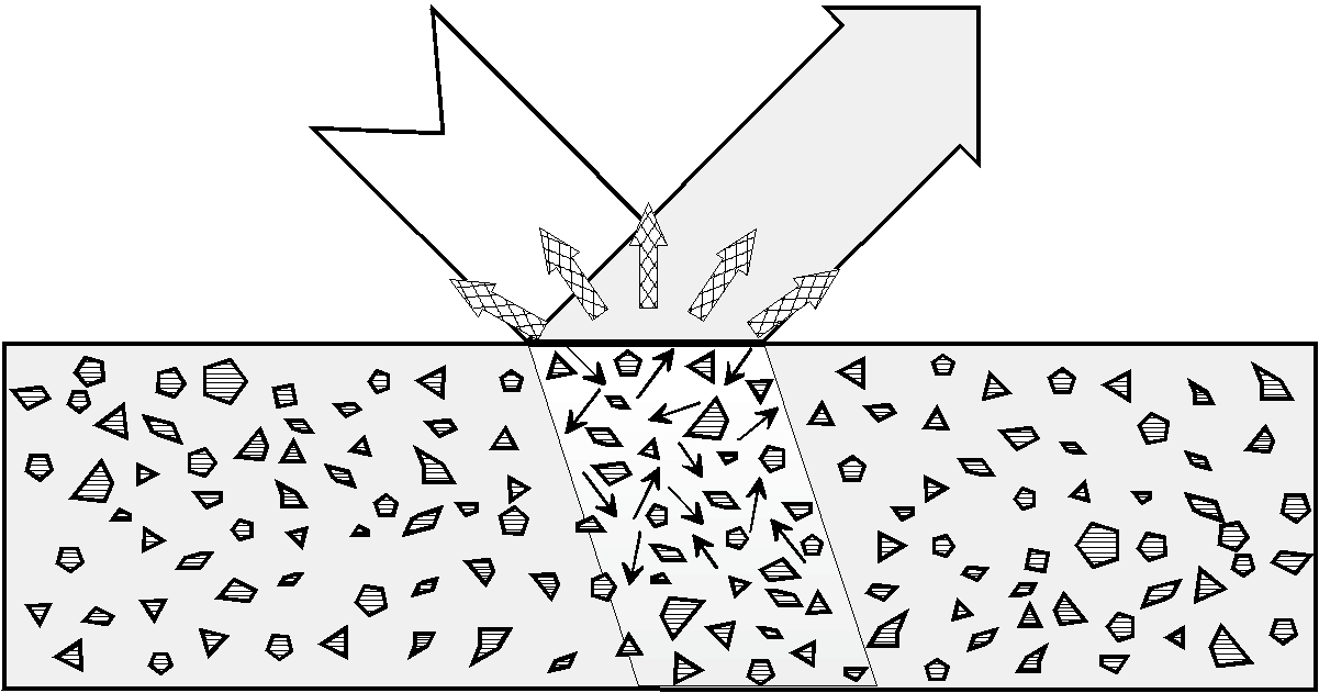
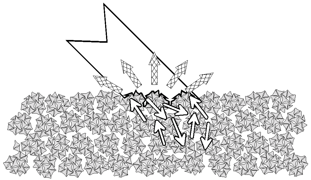
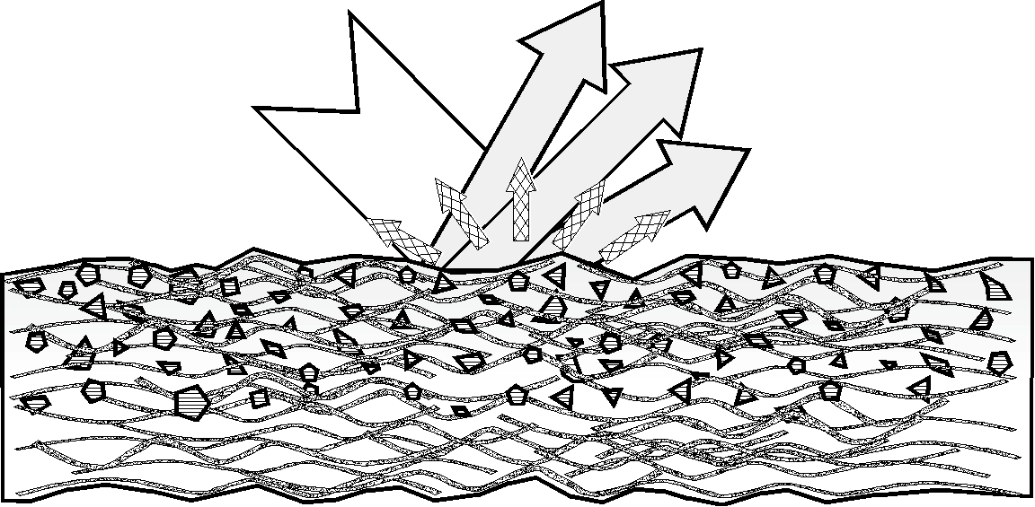
Figure3: Interactions of a light beam at the surface
and within an opaque, pigmented material
Figure
3 is a schematic diagram of the surface region of an opaque, pigmented
material. It has been drawn in an idealised way to show the
different types of interaction that can occur between a light beam and
the various components of the material.
When
a material contains a large amount of pigment, or a coating layer is
thick enough, none of the incident light will penetrate through the
material or the coating layer. The spectrum of the light
reflected from an opaque layer is determined by the absorption and the
scattering properties of the components in the material and does not
change with the thickness of the material. Another property
of an
opaque material is that the addition of a transparent, colourless
diluent to the material will not change its appearance.
Figure 3
shows two types of interaction that take place between the incident
light energy and the material.
Partial
reflection at the air to coating boundary
Absorption
and scattering by the pigment particles within the layer.
These
are discussed in more detail in the following sections.
Light
reflected from within the material
The
light passing through the boundary interacts, through scattering and
absorption, with the pigment particles. If the absorption
occurs
within a selected band of wavelengths in the visible spectrum then the
transmitted light and the reflected light will be coloured.
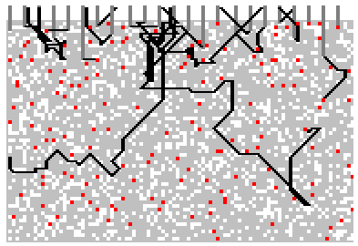
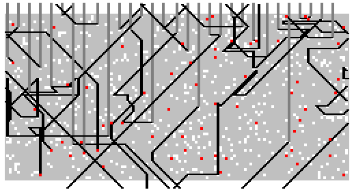
Figure
4 illustrates the paths that photons might take in an opaque, pigmented
material. The figure was obtained by a computer program that
simulates the interactions of an incident light beam with a layer
composed of a clear medium, a white pigment and a coloured tinter
pigment.
Photons
are "fired" at the top surface of the layer and when the photon
encounters a particle, a random number generator is used to decide
whether the photon is absorbed or scattered by the particle.
Figure4: Simulated photon paths, opaque layer
The
figure shows the paths obtained when 30 photons were fired at the
layer. The conditions of the simulation and the result
obtained
are shown in Table 3.
Table3:
Conditions for the computer simulation of light interacting with an
opaque layer
Material
%
PVC
Parameter
%
Value
White
25
Reflection
50
Tinter
5
Transmission
0
Medium
70
Absorption
50
For
a conventionally pigmented material, the direction of the light
transmitted back through the material to air will be spread over a
range of angles. If we exclude the viewing angle that
coincides
with the specularly reflected (mirror like) light, then the colour
impression of the surface is the same, to a good approximation, at all
viewing angles. The exception is at glancing or oblique
angles of
viewing and skilled colourists will often tilt pairs of panels to
compare the colour at both the face and glancing angles of viewing.
Dyed
textile fabrics
A
dyed textile fabric is a single-phase system consisting of the woven or
knitted yarn only. Figure 5 is a depiction of a fabric woven
from
yarn consisting of trilobal fibres twisted together. The
interweaving of the yarns along their length gives mechanical
continuity, both across and through the fabric.
The
cross-sectional view through the fabric suggests that there is no
continuous phase. However, in optical terms, a textile
material
is a two-phase system.
Figure
5: Interactions of a light beam at the surface and within an opaque,
textile material
The
continuous phase is formed by the air and the discontinuous phase is
formed by the textile fibres.
Light
reflected from within the fabric
The
light passing through the boundary is scattered within the fabric at
the internal air to fibre boundaries. The refractive index difference
between the air (refractive index 1.00) and the polymeric fibre
(refractive index of order 1.50) means that the air gaps act as
scattering centres.
Light
travelling within the textile fibres will interact with the dye
molecules. If light absorption occurs within a selected band
of
wavelengths in the visible spectrum then the transmitted/reflected
light will be coloured.
Wet or
damp material
If
the air gaps are filled with a material with a refractive index nearer
to that of the fibre, then the scattering is reduced and the fabric
becomes darker and more transparent. This used to be a cause
of
embarrassment to wearers of pure white swimming costumes made from
synthetic fabrics. Water has a refractive index of 1.33; much
closer to the index of the fibre, the consequent reduction in
scattering when the costume became wet meant that the fabric became
virtually transparent. The same effect occurs when some types
of
T-shirt become wet.
The
problem of the wet transparency of synthetic fabrics can be overcome by
incorporating a very fine dispersion of a light scattering pigment into
the polymer fibre during spinning. Light is scattered within
the
fibres as well as at the air to fibre boundaries.
Homogeneous
semi-transparent materials
Many
printed and coated surfaces are a semi-transparent layer over an opaque
substrate. The coating material is usually composed of a
dispersion of pigment and filler particles embedded in a continuous
medium. Some of the particles in the coating scatter the
light
into different directions and, if the layer is coloured, some of the
particles absorb the light.
Figure
6 is a schematic diagram of the surface region of an object that has
been coated with a layer of a conventionally pigmented
material.
It has been drawn in an idealised way to show the different types of
interaction that can occur between a light beam and the various
components of the material.
The
incident light energy is partially reflected at the air to coating
boundary.
Figure
6: Interactions of a light beam with surface covered with a pigmented
coating layer
The
light that enters the coating layer is scattered and absorbed by the
particles suspended in the layer, some light energy will be reflected
out of the layer and some transmitted towards the interior of the
material. In Figure 6Figure , the opaque substrate material
reflects a portion of the light back towards the illuminated
surface. There is a series of multiple reflections within the
layer, until the light energy is either transmitted back through the
coating to air boundary or is absorbed.
The
spectrum of the light reflected from the surface depends on a number of
factors;
The
partial reflectance at the air/coating boundary.
The
absorption and scattering properties of the coating layer.
The
thickness of the layer.
The
reflectance spectrum of the substrate material.
Figure
7, illustrates the paths that photons might take in a semi-transparent
pigmented layer. The simulation was obtained under the same conditions
as for the opaque material, except that only one third of the volume of
pigment was used.
The
illustration shows the paths obtained when 30 photons were fired at the
layer. The conditions of the simulation and the result
obtained
are shown in Table 4
The
semitransparent layer reflects 30% of the incident light, less than an
opaque layer of the same material. However, 30% of the
incident
light penetrates through the semi-transparent layer.
Table4:
Conditions for the computer simulation of light interacting with a
semitransparent layer
Material
%
PVC
Parameter
%
Value
White
8.33
Reflection
30
Tinter
1.67
Transmission
30
Medium
90
Absorption
40
A
coating layer can be fully transparent. For example, a yellow
lacquer coated onto a foil-laminated carton board will give an
attractive metallic gold appearance. This type of coating absorbs but
does not scatter light. The coating is coloured either by the
addition of soluble dyes or by transparent forms of pigment particles.
Heterogeneous
materials
The
third type of system describes the case when the colorants in the
coating material are partially or totally absorbed into the surface
layers of the substrate. An excellent example is the surface
regions of wood that has been treated with a stain. The
colorants
in a wood stain can be a mixture of dyes dissolved in a carrier solvent
or pigments in suspension, or both. On application, the
carrier
liquid is rapidly adsorbed into the wood surface, transporting the
colorants into the pores and channels between the wood fibres.
Two
other examples of heterogeneous systems are conventional fountain pen
ink written onto paper and newsprint ink printed on newspaper and
low-cost magazines. The colorants are held within the surface
by
physical entrapment and can be rubbed off onto your fingers.
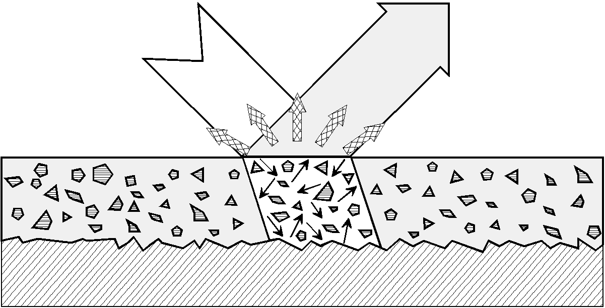
Figure
8 is a schematic diagram of the surface region of an object where the
coating material has been absorbed into a fibrous substrate.
There is more colorant absorbed in the region adjacent to the surface
than in the deeper of the material.
The
incident light energy is partially reflected at the air to coating
boundary.
Figure
8: Interactions of a light beam with surface adsorbed pigmented coating
layer
The
air to coating surface that is shown in Figure 8 is irregular,
consequently the boundary reflected light would be spread over a range
of angles
The
light that passes through the air-to-coating surface is scattered and
absorbed by the substrate and by the colorants. Some of the
light
energy will be reflected out of the layer and some transmitted deeper
into the material. A portion of the light energy is reflected
from the interior back towards the illuminated surface. There
is
a series of multiple reflections within the surface region, until the
light energy is either transmitted back through the coating to air
boundary or is absorbed.
The
spectrum of the light reflected from the surface depends on a number of
factors;
The
partial reflectance at the air/coating boundary.
The
absorption and scattering properties of the coating material.
The
amount of coating material applied per unit area of surface.
The
depth of penetration of the coating material into the substrate.
The
reflectance spectrum of the substrate material.
Partial
reflection of light at a boundary
An air
to coating boundary
The
difference between the value of the refractive index of air and that of
the coating material causes part of the incident light energy to be
reflected at the air to coating boundary. It will be shown in
a
later section that the effect of the boundary reflectance needs to be
taken into account in numerical calculations of the total power
reflected by the surface. The effect is accounted for by the Saunderson correction equation.
Glossy
surfaces
For
a perfectly smooth surface, the boundary reflected beam makes the same
angle with the normal to the surface as that made by the incident
beam. This is identical to the way in which a mirror will
reflect
a beam of light and, for this reason, boundary reflection is also known
as specular (mirror like) reflection. The spectrum of the
boundary reflected light is virtually the same as that as the incident
beam, so if the incident beam is white light then so is the boundary
reflected light. An observer viewing such a surface will see, at
certain viewing angles, reflected images of the surroundings.
This gives rise to the visual impression of gloss.
Matt
surfaces
The
boundary reflectance is present for a rough surface, however the range
of angles that the surface presents to an incident beam causes the
boundary reflected light to be spread over a wide range of
angles. The boundary reflected light is so diffuse that the
observer cannot make out images of the surroundings. Consequently, the
visual impression is that of a matt surface.
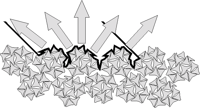
An air
to textile boundary
The
dye molecules are located within the textile fibres, therefore light
has to pass through an air to fibre boundary before it can interact
with the dye. The effective boundary is the perimeter of the
fibres at the illuminated surface of the material, this is shown in
magnification in Figure 9. The boundary outline, for most
textile
materials, is very convoluted, consequently the boundary reflects light
into all possible directions.
Figure
9: Partial reflection at the air to fabric boundary
The
boundary reflected light blends in with the light reflected from the
body of the fabric. The boundary reflectance needs to be
taken
into account in numerical calculations of the total power reflected by
the surface. The effect is accounted for by thePineo correction equation.
Relating
composition to colour
The
structures and light paths shown in the figures illustrate the
complexity of the surface regions of coloured materials. In
particular, examine the figures to obtain an impression of the range of
possible paths that light beams, or photons, might take within these
types of materials.
Lambert
Bougeur law for non-scattering materials
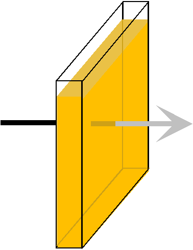
The
Lambert Bougeur law applies to a collimated beam of light passing
through a fixed thickness of material, as illustrated in Figure 10.
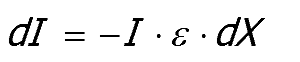
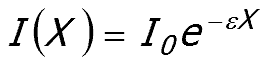
The
law describes the change in the intensity (I)
of a beam of light (dI) as it travels a short distance
(dX) within an absorbing material.
Equation
1
Whereε is the constant of
proportionality.
Integration ofEquation
1gives the intensity of
lightI(X)transmitted through a cell of
thicknessX.
Equation
2
Figure
10: Optical cell
WhereI0is
the intensity of the incident light. The same form of
equation
can also be used for the transmission of a collimated beam of light
through materials that weakly scatter light, provided the amount of
light that is scattered is low, less than 10%.
The
Lambert Bougeur law cannot be used to determine the amount of light
transmitted or reflected by the coloured materials that both absorb and
scatter light. This is because instead of the light
travelling a
single distanceX,
scattering creates a range of distances as illustrated by the light
paths shown in Figures 4 and 7. Some of the paths are
extremely
short, the light beam or photon being directly reflected back by a
scattering particle very near to the surface, other paths are many
times longer and very erratic in direction. There is no
direct
way to determine the value ofX, the path length inEquation 2,for every possible path the light beams might
take.
Schuster-Kubelka-Munk
theory for materials that absorb and scatter light
In
the later sections, the Schuster-Kubelka-Munk theory is used to relate
the reflectance of a material to its composition. Rather than
trying to determine what happens to individual beams of light, the
theory considers the net flow of energy, known as an energy
flux.
The theory is central to a number of national and international
standards for characterising the properties of coloured
materials. It is also the basis of many of the algorithms
used in
some types of computer based formulation prediction systems.
In
order to develop explanations for the influence of the composition of a
material on its colour, it is necessary to define the terms intensity,
power and flux.
Light
intensity, power and energy flux
Intensity
The
intensity of a light beam is the time average of the amount of energy
per second, which crosses unit area perpendicular to the direction of
flow. The units of intensity are Watts per square metre (W m-2).
Intensity is a vector quantity, since the definition includes a
direction.
Power
Power
refers to a total amount of light energy per second, irrespective of
direction. For example, if we want to define the power of the
light emitted by a filament lamp, we would imagine a spherical surface
surrounding the bulb, as illustrated in Figure 10. To determine the
power, the intensities of all of the light beams crossing the surface
of the sphere are added together.
Power
has units of Watts and is a scalar quantity
Figure
10: Power radiated by a lamp
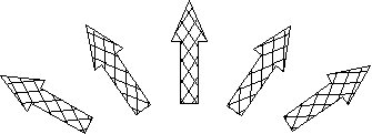
Flux
A flux
of light energy is the amount of energy travelling within a specified
range of directions.
The
Schuster-Kubelka-Munk theory divides the light travelling within the
material into two fluxes.
One
flux includes all the light travelling in directions that have a net
movement towards the illuminated surface, often called the "up flux".
The
other flux includes all the light travelling in directions that have a
net movement away from the illuminated surface, often called the "down flux".