|
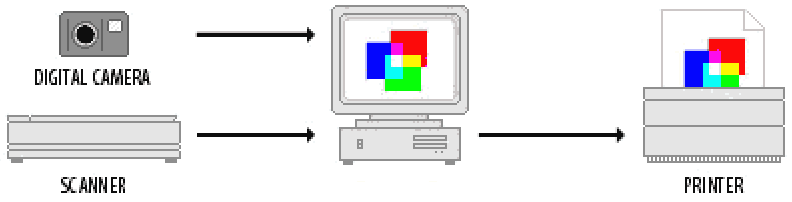
A typical set of devices involved in capturing and reproducing a digital image is shown in Figure 1. At its simplest the reproduction chain of has four stages: |
|
|
© James H Nobbs |
|
|
|
|
Introduction
The challenge of colour image reproduction is to capture a scene and then to display or to print the image with the highest possible fidelity to the appearance of the original scene.
|
A typical set of devices involved in capturing and reproducing a digital image is shown in Figure 1. At its simplest the reproduction chain of has four stages: |
|
(scene capture) – (image storage) – (image display and editing) – (copy production)
The scene information is stored as sequences of colour codes in an image file. The values encoded in the file depend on the device settings during image capture; they provide a device-dependent representation of the image.
Device-dependent colour
Device-dependent colour is the term used to describe the situation when the colours represented by the codes in a colour image file depend on the settings and characteristics of the device used either to capture the image or to reproduce the image. The problem arises because each device may interpret the colour information in its own unique way.
|
|
A scanner or camera interprets an original scene into a data file of RGB codes. The values of the codes will depend on the specifications and settings of the input device. |
|
|
A monitor displays RGB codes as colours on the screen according to the colour characteristics of the display light sources and the settings of the display. |
|
|
The printed colour obtained from a desktop printer depends on the properties of the inks, the properties of the substrate and the way the printer interprets the colour information from RGB codes into amounts of ink and numbers of dots. |
|
|
A commercial printing press produces printed output according to the specifications followed and the type of inks used. |
For example when the image appears "just right" on the PC monitor, the printed copy may not look correct. The devices may not be speaking the same colour language or may not have the ability to reproduce the same range of colours (gamut).
Different colour languages
There are two distinct ways that image information is represented
RGB colour language
Devices such as cameras, scanners and displays record, store and interpret colour information using the RGB colour model. This is a model based on the additive mixing of red, green and blue coloured light emitted from the screen. The colour produced by a device for an RGB code depends on:
|
|
the white point setting of the device; |
|
|
the value of the power law response factor for the device(gamma factor). |
CYMK colour language
Devices such as ink-jet printers, laser printers and printing presses, interpret the colour information using the CMYK colour model. This is a model based on the subtractive effect of three coloured inks, cyan, magenta and yellow along with a fourth black ink (noted as K). The model is based on the absorption (subtraction) of red, green and blue light by the ink layers from the light reflected by a white substrate. The colour produced by a device for a CYMK code depends on:
|
|
The properties of the printing inks |
|
|
The type of substrate |
|
|
The thickness of the ink layers |
Device-independent colour
Device independent colour codes represent the colour using methods defined by international standard organisations, for example CIE XYZ and CIE L*a*b* which are defined by the CIE (Commission Internationale de l'Éclairage).
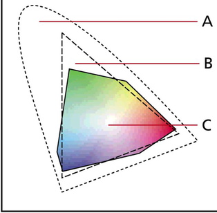
Different colour gamuts
Even the best photographic film can capture only a small portion of the colours discernible to the human eye. A computer monitor can display only a fraction of the visible colours, and a printing press has a similar restricted range of colours that can be reproduced.
Colour management
Unfortunately, when unmanaged, the image representation in an electronic file is uniquely characteristic of the scene capture process and in addition, each copy production device interprets the representation in its own characteristic way. Reproduction of the image with a high level of colour fidelity will require the colour code values to be transformed into appropriate instructions to the specific output device. The values encoded in the instructions are also device-dependent.
|
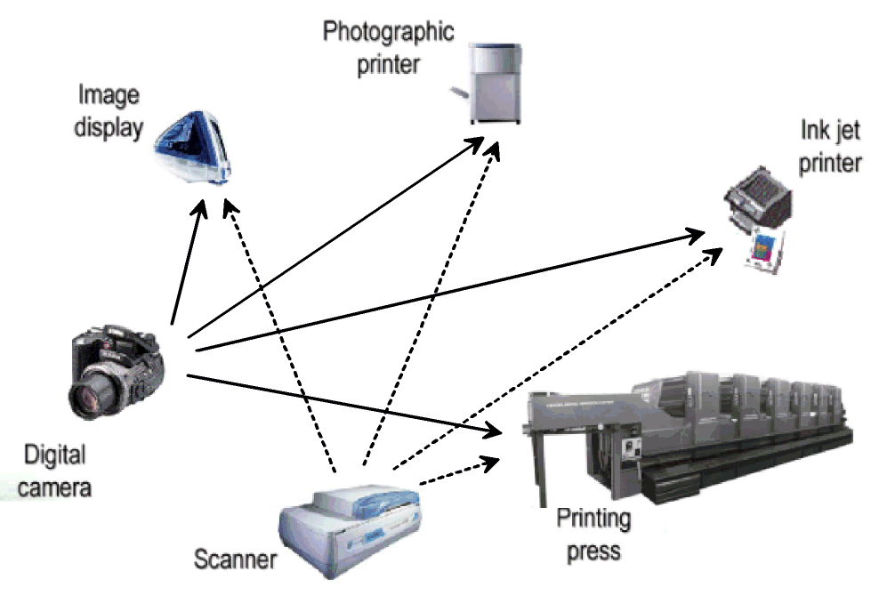
Closed method of management M × N image transformations To obtain satisfactory colour reproduction, the image file has to undergo a transformation for each type of device, as illustrated by Figure 3. If there are M input devices available and N output devices then the number of possible transformations of image information from input to output is M × N. |
Figure 3: Closed method of communicating colour |
|
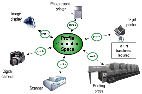
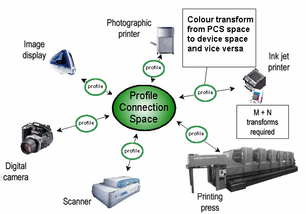
Open method of management M + N image transformations The open method uses a common colour language (profile connection space) to exchange colour information and a single translation file for each device (profile) to convert the device colour language information to and from the common colour language, as illustrated by Figure 4. The number of transformations needed for M input devices and N output devices is M + N. |
|
Colour management system (CMS)
|
There are major problems associated with transferring image information between input and output devices such as shown in Figure 5, and ensuring accurate representation of the colours by each of the output devices.
The problems arise from the different colour languages that may be used by the devices and from differences in the range of colours that can be reproduced by the devices. |
|
The major functions of a colour management system are:
|
|
to give a reliable and predictable interpretation of the colour information stored in image files; |
|
|
to reduce colour matching problems between display and print devices. |
To match screen colours to a printer, a CMS must do the following:
|
|
convert the screen RGB values to device-independent values, such as CIEXYZ; |
|
|
convert the CIEXYZ values to the dot areas C M Y and K for the printer; |
|
|
compare the colour gamut of the screen with that of the printer and map the colours from one device gamut to the other device gamut. |
Graphic software applications that utilise a colour management system are able to reconcile the different colour capabilities of cameras, scanners, monitors, printers, imagesetters and printing presses.
ICC Colour management system
In 1993, members of the computer and colour publishing industry began working toward a common approach to colour management. They formed the International Colour Consortium (ICC) to establish colour standards that would help users achieve reliable and reproducible colour throughout the reproduction process. They also endorsed an open framework for developing colour management systems.
The ICC colour management model assigns the responsibility for colour transformations and gamut adjustments to the operating system of the computer. This means that colour management is available to all applications.
|
The ICC system makes use of three major components: |
Standard colour language |
|
|
Device profile files |
|
|
Gamut adjustment method |
Colour language (profile connection space)
A standard colour notation is defined that is based on a device-independent colour space. This is also known as the Profile Connection Space (PCS).
The colour values are determined using the default illuminant and observer conditions for the graphic arts industry; CIE D50 Daylight and the CIE 2 degree standard observer functions. Either CIEXYZ or CIEL*a*b* may be used.
Device profile file (ICC profiles)
The device profile file contains the instructions and information necessary to characterise the colour properties of a device.
Figure 5 gives an illustration of the way in which the device profile and the profile connection space are used by the CMS to convert image data between the input and output device.
When colours consistent with one device's gamut are displayed on a device with a different gamut, a CMS uses gamut mapping to optimise the displayed colours between the two devices. The CMS does this by mapping the out-of-gamut colours into the range of colours that can be produced by the destination device.
Gamut adjustment (rendering intent)
A set of standard objectives is given by the ICC for the process of converting the gamut of colours in an image to a set of colours that can be produced by the display or by the output device.
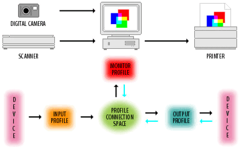
Overview of the flow of information
|
The CMS manages the flow of colour information between the input, display and output devices, as shown in Figure 6.
Input: The device-specific colour notation used by an input device is mapped, by the CMS using the device profile, into the notation of the PCS.
Output: The CMS, using the information in the output device profile, adjusts the colour information for the gamut of the output device and maps from the notation of the PCS into the notation of the output device. |
|
ICC device profiles
A colour management system must have available to it the characteristics of each device in the production process, namely their colour "behaviours" and colour gamuts. This information is stored in files called device profiles. A device profile enables the CMS to convert between a device's native colour notation and the notation used in the Profile Connection Space, as illustrated in Figure 6.
Device profile files are classified into three types:
|
Input profiles: |
for devices such as scanners and digital cameras (also known as source profiles) |
|
Display profiles: |
for devices such as monitors and flat panel screens |
|
Output profiles: |
for devices such as printers, copiers, film recorders |
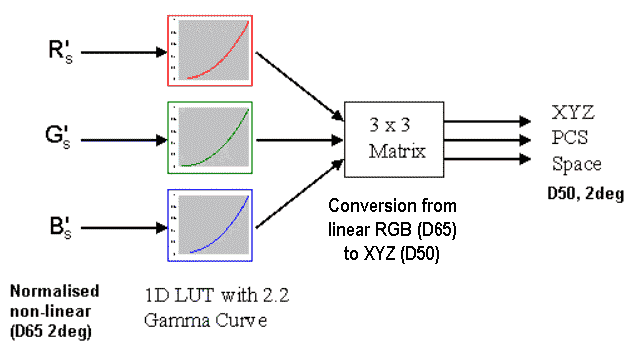
Input profile: digital camera
The profile file also has a set of nine coefficients for a [3 × 3] matrix that converts the linear RGB (D65) values into XYZ (D50) values,
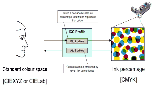
Output profile: inkjet printer
The simplest output profile consists of a set of look-up tables (LUT), which are used to translate XYZ or LAB values into the colour notation of the device.
Profiles can also be embedded within an image date file itself. Embedded profiles allow for the automatic interpretation of colour information within the file as the colour image is transferred from one device to another.
ICC gamut mapping, (render Intent)
A CMS maps colours from one device's colour space to another according to the render intent. The render intent determines how the CMS maps colours. The four render intents in the ICC system are
perceptual, saturation, relative colorimetric, and absolute colorimetric.
Perceptual
The perceptual render intent is primarily intended for photographic images where the perception of image quality is strongly dependent on maintaining the relative relationship between the colours in the image.
When one or more colours in the original image are out of the gamut of the destination device, the rendering process shrinks the gamut of the image, preserving the relative relationship between the points in the gamut, to fit into the gamut of the destination device. All colours in the image are changed, including those that were inside the gamut of the destination device.
Saturation
This render intent is primarily designed for business graphics such as charts and organisational diagrams, where the exact relationship between colours (such as in a photographic image) is not as important as are bright saturated colours.
The rendering preserves the relative saturation (vividness) of the image colour relative to the source primaries by mapping to the colour with the same degree of saturation relative to the destination primaries.
Absolute colorimetric
This render intent is valuable for rendering "signature colours", those colours that are highly identified with a commercial product such as the yellow used by the Eastman Kodak Company, or the red used by the Coca-Cola Company.
This rendering process does not change colours that are in the gamut of the destination device. Out of gamut colours are mapped to the reproducible colour with the nearest hue, with the matching of lightness and saturation being treated as less important.
This render intent can cause two colours, which appear different in the source colour space, to be the same in the target colour space. This is called "clipping”.
Relative colorimetric
When a colour in the current colour space is out of gamut in the target colour space, it is mapped to the closest possible colour within the gamut of the target colour space, while colours that are in gamut are not affected. Only the colours that fall outside of the destination gamut are changed.
Relative Colorimetric Rendering works the same way as Absolute, except that it scales the white of the source to the white of the target. Use this rendering intent for proofing when simulating the paper colour isn't critical.
Creating the profile of a device
Measuring devices, standard colour samples and software applications are available that allow device profiles to the determined. In each case the colours generated by a device are measured to obtain the XYX and L*a*b* values. The software compares the measured values with the values of the standard colours and generates the profile for the device.
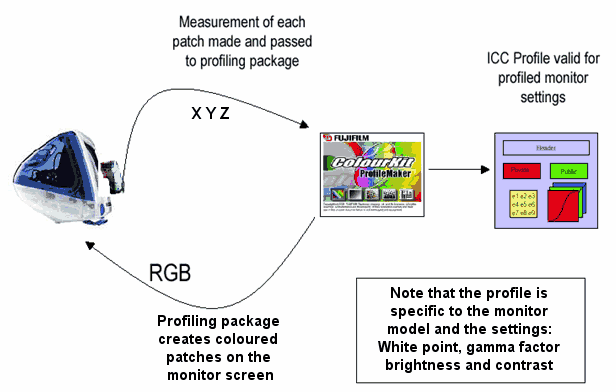
PC monitor
The equipment that is needed is a screen colorimeter for determining the colour of the light emitted by the display, and a software application for carrying out the tests and generating the profile.
The monitor is switched on and the settings put into the desired state. These include the white point, gamma factor, brightness and contrast. Note that the profile that is obtained is specific to these settings.
|
After sufficient time has passed for the colour on the screen to become stable the software application displays a sequence of coloured patches on the screen, the colour characteristics of each patch are measured by the screen colorimeter. The software application compares the intended colour with the achieved colour and generates the device profile. The operation is illustrated by Figure 9 |
|
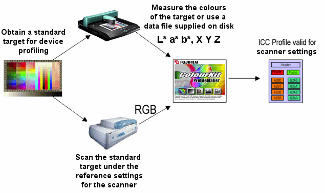
Scanner
A similar sequence of steps is used to create a device profile for a scanner. The equipment needed is a standard colour target, a colorimeter for determining the colours of the standard and a software application for carrying out the tests and generating the profile.
The scanner is switched on and the settings put into the desired state. These include the gamma factor for each R G B channel. Note that the profile that is obtained is specific to these settings.
|
After sufficient time has passed for the light level of the light source and the sensitivity of the device to become stable, the software scans the target colour standard. The colour of each patch is characterised by measurement with a colorimeter or by data values supplied by the manufacture of the standard. The software application compares the intended colour with the achieved colour and generates the device profile. The operation is illustrated by Figure 10. |
|
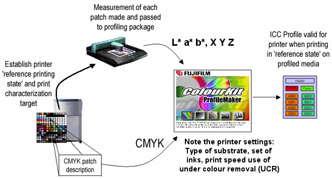
Printer
A similar sequence of steps is used to create a device profile for a printer canner. The equipment needed is a standard image to be printed, a colorimeter for determining the colours of the print the standard image and a software application for carrying out the tests and generating the profile.
The printer is switched on and the settings put into the desired state.
|
These settings include the substrate and the ink set that will be used. Note that the profile that is obtained is specific to these settings.
The colour characteristics of each printed patch are measured by the colorimeter and the software application compares the intended colour with the achieved colour and generates the device profile. The operation is illustrated by Figure 11. |
|
Advantages of an open colour management
|
|
Open colour management lets you compensate for the differences in the characteristics of devices and communicate colour in a device-independent manner. |
|
|
The image capture, design and production workflow is no longer confined to a closed system, but may be distributed across many different systems. |
|
|
It simplifies the introduction of new devices from different vendors into a system and the rapid establishment of accurate colour representation by the new devices. |
|
|
|
|
© James H Nobbs |