|
© James H Nobbs |
|
|
|
|
H42: Image RGB to Display Colour XYZ
Factors involved
The relationships used to model each of the steps are given in the following sections.
RGB Colour codes
The most common level of colour resolution for each picture element (pixel) of a computer display is is 8-bits in each of the R, G and B codes using a total of 24 bits per pixel. This gives 256 levels for each channel (codes 0 to 255) and is sufficient for 16.8 million different R G B codes.
256 x 256 x 256 = 16.8 million codes
At first sight, this seems like a huge number of colours, easily able to satisfy the human eye. However the 16.8 million codes, although equally spaced throughout RGB space, are not equally spaced visually. The colours of neighbouring codes in some areas of RGB colour space are indistinguishable from each other, whilst in other areas the colour difference is easily seen. RGB space is visually non-uniform.
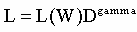
Under the optimal conditions the following equation is assumed to apply:
|
|
|
L is the luminance (brightness in lumens) of the light emitted by the phosphor dots, L(W) is the maximum luminance of the screen and D is the normalized signal (range 0 to 1) applied to the display.
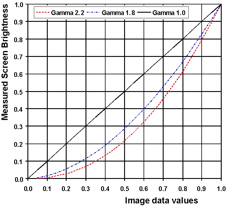
The standard or default gamma value depends on the type of system, typically
|
|
Display gamma = 1.8 for Apple Mac PC systems (and for broadcast TV receivers); |
|
|
Display gamma = 2.2 for a Microsoft Windows PC monitor |
Figure 2 shows the relationship between the normalised pixel data values and the screen brightness for each of these gamma factors.
White point
The white point of a display refers to the characteristics of the light emitted from the screen when the data values are all set to maximum, R = 255, G = 255 and B =255 for example. The nature or “shade” of the white can usually be set in software to suit different applications of the display.
There are four white points in common use for computer displays and they are based on the daylight specification system of the CIE.
The maximum brightness of a display occurs when it is showing white. If this level of brightness is represented as 100 units, then the contributions of the red LR(W), green LG(W) and the blue LB(W) light emitted by the screen to the 100 units depends on the white point setting of the display.
The red luminance [LR(W)] decreases while the blue luminance [LB(W)] increases.
The absolute brightness of a display will depend on the settings of the controls of the display, such as the brightness and contrast and the white point. For conventional displays the order of increasing absolute maximum screen brightness is D50, D65, D75 and brightest is the Windows default of D93.
Colour values of emitted light
The colour values, in terms of CIE XYZ units, of the light emitted by an electronic display are set by national and by international standards.
|
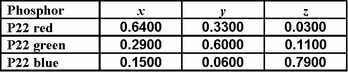
The values for the PC monitors and for the PAL (European) type of television displays are virtually the same as those used in the international standard system for RGB codes, sRGB. The defining values are shown in Table 2. |
Table 2: The chromaticities of the light emitted by a display
|
Remembering that the Y tristimulus value describes the relative luminance of the light, the data given in Table 2 can be used to determine the contributions to the screen X, Y and Z from each type of light emitted by the screen.
|
Each unit luminance of red light will contribute |
X = 1.9394, |
Y = 1.0000, |
Z = 0.0909 |
|
Each unit luminance of green light will contribute |
X = 0.5000, |
Y = 1.0000, |
Z = 0.1667 |
|
Each unit luminance of blue light will contribute |
X = 2.5000, |
Y = 1.0000, |
Z = 13.1667 |
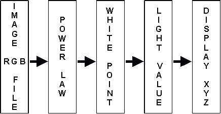
Conversion of R G B to display colour
The steps involved are:
|
|
Normalise the digital codes R G B into the range 0 to 1. (R' G' B') |
|
|
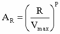
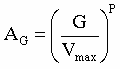
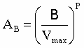
Using the power-law factor for the display system, transform the normalised values to the level of activation of the red, green and blue light emitters. (AR AG AB) |
|
|
Using the white point setting of the display, determine the luminance of the red, green and blue light emitted by the display. (LR LG LB) |
|
|
Using the contributions to X, Y and Z of unit luminance of each type of light, determine the XYZ values for the emitted light. (X Y Z) |
Re-scale data codes to range from 0 to 1, (R' G' B')
We start by setting Vmax as the number corresponding to the maximum code that can be given. The digital codes in the image file are then re-scaled from the range (0 to Vmax), to the range (0 to 1).
For an 8 bit code (24 bit colour), Vmax = 28 -1 = 255
|
|
|
, |
|
and |
|
Relative brightness of each light source, (AR AG AB)
Apply the display power-law factor
The brightness of the image area relative to the brightness when displaying the white point is obtained by applying the non-linear transformation to the normalised data. The values are in the range 0 to 1 and can thought of as the level of activation of the light emitters in that area of the display (AR, AG and AB).
|
|
|
, |
|
and |
|
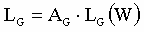
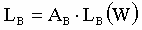
Brightness emitted (LR LG LB)
Take into account the white point settings
Finally the brightness of the red, the green and the blue light emitted from the image area of the screen is determined by multiplying the activation with the white point luminance. The notation LR LG and LB is used to indicate the relative brightness of the red, the green and the blue light emitted by the display respectively.
|
|
|
, |
|
and |
|
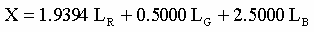
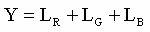
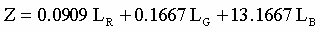
Tristimulus values of the emitted light (X Y Z)
The CIE XYZ tristimulus values for the light emitted by the screen are obtained by summing the contributions to X, Y and Z made by the red, the green and the blue light emitted from the screen.
The colour properties of the light is defined by the display standards, for example the sRGB standard specifies the contributions to X Y and Z of unit brightness of each type of light so that.
|
|
|
|
|
|
|
|
|
Colour resolution
The 16.8 million codes, although equally spaced throughout RGB space, are not equally spaced visually. RGB space is non-uniform and the colours of neighbouring codes in some areas of RGB colour space are indistinguishable from each other, whilst in other areas the colour difference is easily seen.
Research suggests that at least 10 bits per colour code are required in order for the difference in colour between neighbouring codes to be less than the resolution of the eye, throughout the entire gamut.
|
|
|
|
© James H Nobbs |