|
H41: Reproduction of Images: Colour Displays
|
©
James H Nobbs
[Colour4Free]
|
|
|
|
The two major methods of
reproduction of images are visual displays and the four-colour printing
process. Both of these methods are based on the trichromatic
nature of colour vision. The wide range of colours seen in
the reproduced image is created by controlling the amounts of light in
the red, the green and the blue wavelength bands received by the eye.
The most common method of
generating colour by the additive system is visual display units, such
as computer display screens and television screens. Visual
display screens are composed of individual dots, which, at normal
viewing distances, are too small to be seen and the picture appears
continuous. In an image on a video display screen the dots
are of constant size but of various degrees of brightness from black to
full intensity.
Creating
the displayed image
The image on a display screen
appears to be present all of the time, but in fact the brightness of
each part of the screen is flashing on and off many times in each
second. The flashing of the screen is more rapid than can be
followed by the eye and, as a result of “persistence of vision”, the
image appears to be continuous.
In video displays the image
is built up from a sequence of pulses of light that are move across the
screen in a series of lines across the screen and down the
screen.
|
A
typical interlaced scan sequence that is used in television screens is
shown in Figure 1. From “start “ the spot of light moves left
to right tracing out the “odd” lines making up Frame 1 (heavy lines) of
the image. The spot then flies upwards and fills in the
“even” lines (light lines) of Frame 2. The scanning sequence
is also known as a raster. If the complete image is scanned
within 1/25 second and the sequence repeated many times per second,
then your eye will not distinguish the separate pulses and the
perception is of a flicker free image.
|
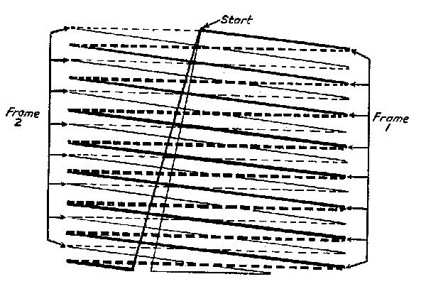
Figure
1: Interlaced scan sequence to create an image on a PAL
(European) display screen
|
Image
capture
A video camera or a scanner
captures an image, by cutting the field of view into a number of thin
slices or lines. Each line is “scanned” in succession and the
variation in brightness along the line forms a sequential stream of
information. The sequential stream of information is encoded
into digital format for example, or into the composite video signal of
broadcast TV.
Image
reproduction
To reproduce the image, the
stream of information is decoded and used to control the intensity
emitted by each little spot scanned along the length of a line on the
video screen. The display builds up the slices again,
reproducing each line in the same sequence as the image capture.
Persistence
of vision
Video display screens make
use of the property of the eye known as “persistence of
vision. If you view a picture for a fraction of a second, and
then take the picture away, the eye will continue to “see” it for a
short time after. In humans, a short pulse of light persists
in visual impression for about a 1/15 of a second.
Early television
Image capture, analysis
John Logie Baird made the
first successful television transmissions between 1928 and
1935. Baird used the BBC’s medium wave transmitters that were normally
used for radio broadcasting.
|
In this system the
pictures were composed of only 30 lines and small details could not be
reproduced, this was a low-definition television system.
The
first cameras and receivers were almost entirely mechanical in
operation, and looked very different from modern equipment.
Figure 2 is an illustration of one of Baird’s
experimental cameras. Baird used a system of apertures cut
into spinning disks to slice the image into 30 lines at a rate of ten
images per second.
|
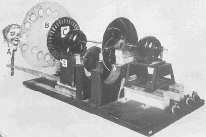
Figure 2: Baird’s
experimental camera capable of producing 10 images per second each
composed of 30 lines
|
Image
display, synthesis
Bairds’
receivers, like the cameras, were semi-mechanical in operation and
looked very different from a modern television, as shown in Figure 3
and Figure 4.
A disk within the receiver
was spinning at exactly the same rate as the disk in the
camera. The disk had a number of slots cut into the
surface. The slots passed in front of a neon lamp, generating
a view of the lamp as a sequence of lines. The intensity of
the light emitted by the lamp was pulsed on and off in the same
sequence as the variation in brightness detected by the
camera. In this way the image was recreated line by line so
that a continuous image was clearly seen by the viewer.
|
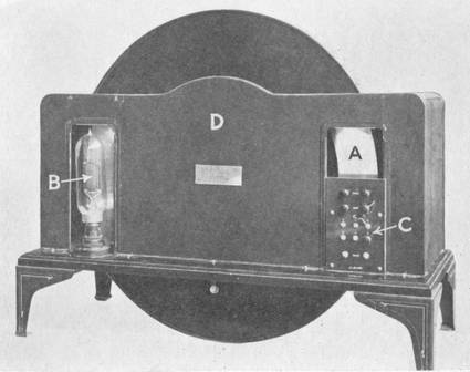
Figure 3: Baird receiver, rear
view showing the
spinning disk A and the neon
lamp B
|
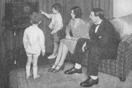
Figure 4: The Baird Televisor
|
To the viewing public, it
seemed more like magic than science. As a newspaper report
stated “Actions taking place far away are reproduced by the combined
magic of light, electricity, ether waves and delicate mechanical
apparatus”
Image reproduction, visual displays
The most important type of
visual display makes use of the cathode ray tube (CRT).
Historically this was the first type of colour display for television
and computers and the colour standards for visual display systems are
mainly based on the properties of CRT systems.
|
Figure
5 illustrates how light is generated in a CRT type of
display. The screen of a CRT computer display or television
receiver is coated with tiny dots of rare earth phosphors that are
electroluminescent. Within the picture tube, an electron beam
is scanned across the screen and when it hits one of the phosphor dots,
the kinetic energy of the electrons is absorbed by the phosphor and
transformed into light and heat energy. The light emitted is
a characteristic colour and the amount of light depends on the kinetic
energy of the electrons in the beam and the intensity of the beam.
|
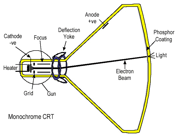
Figure 5: Process of light
generation in a CRT
|
This type of display creates
the range of colours by means of the additive colour mixing of light
from three types of electro-luminescent phosphors.
Additive
colour mixing
The additive primary lights
are red, green and blue in colour, are chosen to be able to reproduce a
wide gamut of colours.
|
The individual red,
green and blue light emitting phosphor dots are close together and are
not resolved by the eye so that the eye perceives the combined
(additive) colour.
Additive colour mixing
leads to some surprises, as shown in the colour-mixing diagram, Figure
6. For example, the eye blending together light from the red
light emitting dots and the green light emitting dots creates the
impression of yellow in an image. Yellow is one of the
subtractive colour primaries, the other two subtractive primaries are
obtained when green light and blue light are blended (cyan) and when
red light and blue light are blended together (magenta).
|
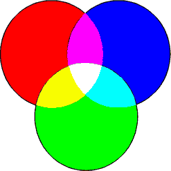
Figure 6: Additive colour mixing
|
Shadow mask display system
|
Close
examination through a magnifying glass of a conventional “shadow mask”
computer display screen or television screen reveals a sequence of dots
of red, green and blue emitting phosphors.
The
phosphor dots are grouped as “triads”, that is a red, a green and a
blue dot arranged in a triangle as shown in Figure 7. Each triad on the
screen is known as a pixel, this is the smallest area (a picture
element) of the image that can be resolved.
If
the space between the phosphors is filled with black, then the
impression of a brighter image of higher purity is obtained.
|
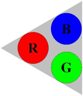
Figure 7: Phosphor dot triad
|
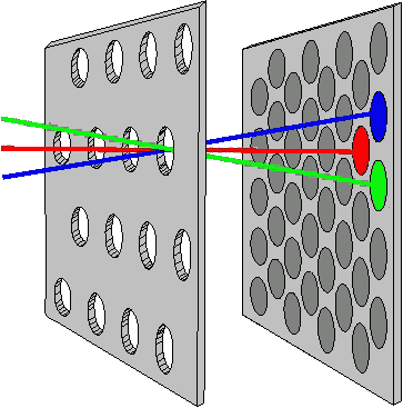
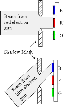
There are three separate
electron beams present in a colour cathode ray tube display.
The beams scan across the phosphors on the screen, one beam
corresponding to each colour channel.
The electron guns that
produce the beams are in a triangular arrangement and each of the three
beams of electrons arrives at the screen at a slightly different angle,
as shown in Figure 8.
|
A
metal mask, the “shadow mask”, is between the guns and the
screen to ensure that each gun activates only one phosphor within each
triad. The success of the shadow mask in keeping the wrong
dots from activating determines the “purity” of colour reproduction.
Good
colour and spatial resolution is achieved by having a large number of
phosphor dots, each group as close together as possible.
|
|
|
|
Figure 8: Action of the shadow mask in
directing the electron beam onto the correct phosphor dot
|
Sony Trinitron display system
The principle of the
Trinitron display system is the same as that described above however
the phosphors are laid down as light emitting strips instead of
dots.
|
The
arrangement of is illustrated in Figure 9. Three electron
guns lying in the same horizontal plane emit three beams of
electrons. A metal aperture plate with vertical slots is used
instead of a shadow mask to ensure that each beam hits the correct
strip.
The
horizontal arrangement of the electron guns makes the Trinitron display
tube cheaper to manufacture than the shadow mask tube.
|
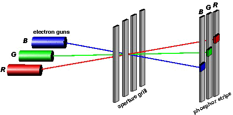
Figure 9: The Trinitron,
aperture grill system
|
The efficiency of conversion
of electron energy to light energy is higher, because in the triad
system the shadow mask stops a lot of the electron beam’s
energy. However, the spatial resolution of the Trinitron
system is, potentially, not as good as with the triad system.
LCD displays
In a LCD, the screen consists
of a liquid crystal cell illuminated by an internal
back-light. Transparent electrodes are evaporated onto the
inside surfaces of the two glass plates that hold the liquid crystal,
as shown in Figure 10
|
In
the ‘liquid-crystal’
phase, the material’s molecules exhibit partial order.
The liquid crystal molecules will allow polarised light to be
transmitted through the display until a voltage is applied to the
electrodes. When subject to the electric field, the liquid
crystal molecules take another orientation and the second polariser now
blocks the light. By applying an electrical pulse, the liquid
crystal acts like a shutter switching the light transmission of the
cell on and off.
Each
LCD pixel consists of three cells, with a red, green or blue colour
filter placed over each portion. In this way colour is
produced in a similar way to the shadow-mask system.
|
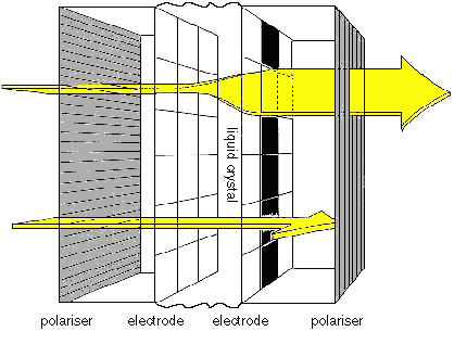
Figure 10: A cross-section of an
LCD display
|
To increase sensitivity
transistors can also be placed at every cell to act as a fast
switch. The colour gamut is in quite good agreement with the
conventional display standards, but brightness is not as good as the
conventional display. The advantages to using LCD’s
are that they are far more efficient in terms of power than CRTs and
that they can be made very compact in size.
R G B values
Three numbers, R G and B in a
graphic image file on a computer describe the colour of each pixel in
the image. These represent the relative
amounts of red, green and blue light respectively, that are to be
emitted by the phosphors at that point on the display screen.
The units of R G and B are tristimulus units or “T units”.
This type of unit is defined so that a mixture containing equal T unit
amounts of the standard red, standard green and standard blue light
sources will match the appearance of a defined white light source,
known as the white point of the display. For example, if an
area of the graphic image is set to R=255, G=255 and B=255 then it will
have the colour characteristics of the display white point.
White
point of the display
Three different white points
are in common use and the software for modern computers often allows
you to adjust the white-point of your monitor, which will change
appearance of the images on the screen.
Broadcast TV (D65 average daylight,
colour temperature 6500K)
The white point standards for
broadcast television (terrestrial EBU PAL, satellite and HDTV) is
average daylight (D65) under the CIE 1931 observer. The white
point for the US TV system is D75, daylight with a colour temperature
of 7500 K.
PC
screens for office use (D93, colour temperature 9300K)
The white point of computer
monitors are set to a high colour temperature (9300K) in order to get
more light out of the blue phosphor and make the display more visible
in well-lit offices.
PC
Screens for the graphic arts (D50, indoor daylight colour temperature
5000K)
In monitors designed for
graphics-arts applications and desktop publishing, the white point is
D50, .
Gamma factor of a display
You might expect that the
light output from an area of the screen is linearly dependent on the
RGB values of the image. In other words, if the R G B values
are doubled then twice the intensity of light will be emitted from the
screen. For CRT displays, this is not the case; if the RGB
values are doubled then about four times the intensity will be emitted
from the screen.
The phosphors in a CRT
display produce light by converting the kinetic energy of the electrons
in the beam to light energy. The kinetic energy is
proportional to the square of the speed of the electrons. As
a result the intensity of the light emitted by the phosphor is
proportional to the R G B value raised to a power of approximately
2.0. The power law coefficient is known as the gamma factor,
and the standard value for the PAL system is 1.80.
|
When the gamma factor
for a display is correctly set, an area of mid grey with R =50%, G =
50% and B= 50% (Figure 11, right) will give the same grey perception as
the "merged" impression from a fine pattern of dots with 50% of the
area set black and the remaining area set as white (Figure 11 left).
|

Figure 11: Gamma factor test
image. A 50% grey(right) and an area with 50% black and 50%
white(left).
|
When the gamma factor for the
display is set correctly, the two rectangles will have the same
lightness. When the gamma factor is not correctly set, the
right rectangle will appear to be either lighter (display gamma too
high) or darker (display gamma set too low) than the left
rectangle. The software supplied with many types of modern PC
graphics driver cards allow the user to set the gamma factor used by
the display.
Quality
of reproduction
Colour gamut
It is not possible to
reproduce all the colours that the human visual system can perceive by
blending together light from three coloured sources. The CIE
x y chromaticity chart shown in Figure 12 provides a way of displaying
the colour gamut of the visual system. The full colour gamut,
bordered by the spectral colours, lies within the horseshoe
shape. The display gamut is contained within the triangle
joining the points labelled R, G and B. Figure 12 correctly
shows the area of the screen gamut relative to that of the full gamut.
|
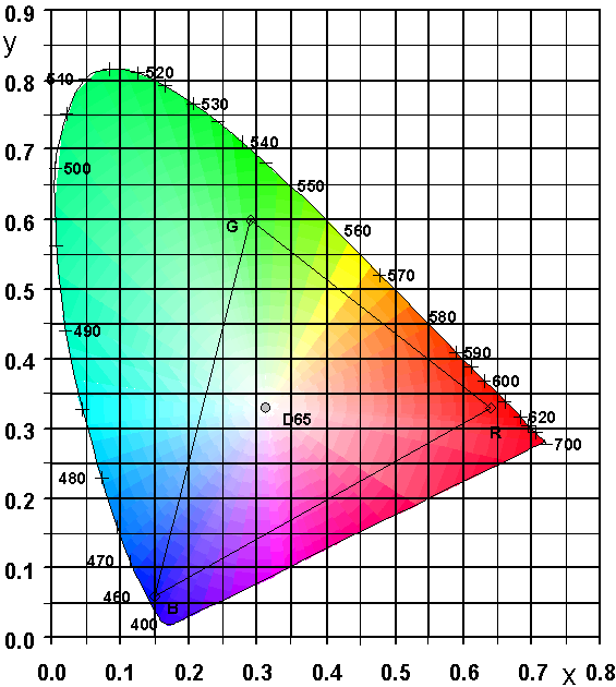
Figure 12: Colour gamut of PAL
(EBU) phosphors
|
Viewing conditions
In order to give good colour
reproduction, the display screen should be viewed in subdued lighting,
and should have a neutral grey surround around the screen.
The user should wear dark clothing, since the screen’s
surface can be highly reflective – typically 4% to 18% - and surface reflections
distract the user from a proper assessment of the image.
Colour
resolution
The most common level of
colour resolution used with personal computer screens at present is
8-bits in each of the R, G and B channels, 24 bits per pixel.
This gives 256 levels for each channel and is sufficient for 16.8
million different R G B codes.
256 x 256 x 256 = 16.8
million
At first sight, this seems
like a huge number of colours, easily able to satisfy the human
eye. However, the fact is that the 16.8 million, although
equally spaced throughout RGB space, are not equally spaced
visually. RGB space is highly non-uniform, neighbouring
colours in some areas of RGB colour space are indistinguishable from
each other, whilst in other areas the colour difference is more than
ten times greater than the resolution of the eye. Colours
spaced equally throughout 24 bit RGB space appear to the eye to have
colour difference steps varying in size by as much as 30:1 through the
different regions.
|
|
|
|
H41: Reproduction of Images: Colour Displays
|
©
James H Nobbs
[Colour4Free]
|