|
(scene capture) |
(image
storage)
|
(copy production) |
|
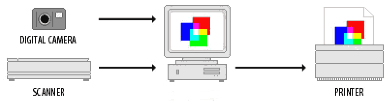
Figure 1: Publication chain for the home-office reproduction of coloured images |
||
|
H34: Putting Numbers to Colour: sRGB |
© James H Nobbs |
|
|
|
Introduction
The challenge of publishing multicoloured images is to capture a scene and then to display or to print the image with the highest possible fidelity to the appearance of the original scene.At its simplest the publication chain of has the stages that are illustrated by Figure 1:
|
(scene capture) |
(image
storage)
|
(copy production) |
|
Figure 1: Publication chain for the home-office reproduction of coloured images |
||
Problems arise from the use of devices with different principles of operation and different capabilities for colour production. The devices used at each stage in the chain represent and interpret the colour information in their own unique way. Without the use of a Colour Management System (CMS), the colour obtained at one stage of the process rarely matches that obtained at another stage.
|
|
A scanner or camera interprets an original scene into a data file and the values of the RGB codes will depend on the specifications and settings of the scanner. |
|
|
A monitor displays RGB codes as colours on the screen according to the colour characteristics of the light emitters and the settings of the display. |
|
|
The printed colour obtained from a desktop printer depends on the properties of the inks, the properties of the paper or card and the way the printer interprets the colour information from RGB codes into amounts of ink and numbers of dots. |
|
|
A commercial printing press produces printed output according to the press conditions, the type of paper or board and the type of inks used. |
The colours produced or displayed from an image information file depends on the characteristics of the device, this is often called device-dependent colour. As a result, the time and effort spent using a graphics application to edit an image file until the results appear "just right" on the PC monitor may be wasted because the a printed copy often does not look correct.
RGB colour language
Devices such as cameras, scanners and displays record, store and interpret colour information using the RGB colour model. This is a model based on the additive mixing of three coloured lights; mixtures of red, green and blue light are used to represent colour information and to display colours on a screen.
The colour represented by an RGB code depends on the white point setting of the device and on the value of the power-law adjustment factor. A power-law adjustment process (gamma factor) is used to compensate for the non-linearity between the code value in the image file and intensity of light produced by some types of display device.
Resolution of digital colour codes
The most common level of colour resolution for each picture element (pixel) of a computer display is is 8-bits in each of the R, G and B codes using a total of 24 bits per pixel. This gives 256 levels for each channel (codes 0 to 255) and is sufficient for 16.8 million different R G B codes.
256 x 256 x 256 = 16.8 million codes
At first sight, this seems like a huge number of colours, easily able to satisfy the human eye. However the 16.8 million codes, although equally spaced throughout RGB space, are not equally spaced visually. The colours of neighbouring codes in some areas of RGB colour space are indistinguishable from each other, whilst in other areas the colour difference between neighbouring codes is easily seen.
Colour gamut of digital codes
|
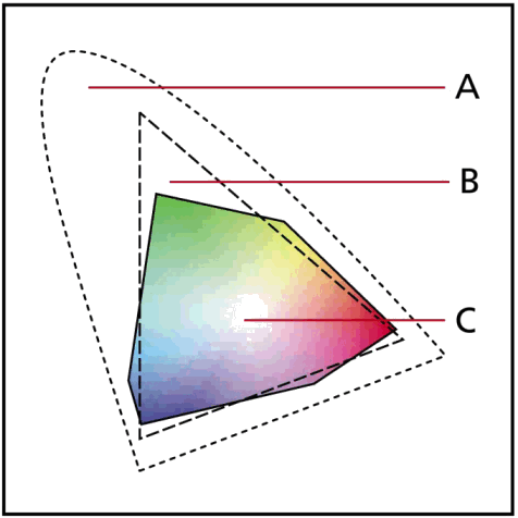
It should be noted that a computer monitor cannot display all of the colours that can be seen by the visual system.
The hue and saturation of the colours that can be reproduced by typical display device and by a typical inkjet printer device are shown in Figure 2. In general the diagram shows that RGB monitors can display more colours than a typical photo-quality inkjet printer, but there are some print colours that cannot be reproduced on-screen. |
Figure
2: x y chart of colour gamut,
|
sRGB colour space
In the community of devices and industries that communicate colour information with R G B, there are many confusing and often incompatible R G B practices and standards. Exactly which colour is represented by the R G B data stored in an image file is not well defined. The objective of sRGB is to provide a workable solution that solves most of the colour communication problems for office, home and web users.
The sRGB system is compatible with current industry practices, in particular with the broadcast television industry. The standard is also compatible with the majority of image collections. Some collections contain over a million images.
The sRGB colour space is based on the image display system defined in the HDTV standard (high definition television). The colour space has been standardised by the International Electrotechnical Commission (IEC) as IEC 61966-2-1.
Compatibility of sRGB with the PC colour management system is important in order to provide a bridge between the sRGB “mass market solution” and high end or niche solutions based on ICC profiles. Hewlett Packard developed and released a master ICC profile for sRGB devices and the profile is included within every Microsoft operating system. Look for the file:
sRGB Color Space Profile.ICM
sRGB device settings
White point (D65)
RGB systems are designed so that when the value of the R, G and B codes are all at the maximum then the colour represented is white. Many PC displays and colour management systems offer a choice of four white point settings, (D93, D75, D65, D50).
|
|
D93 |
Is the default setting for the Windows Operating System |
|
|
|
D75 |
Is the white point of the terrestrial broadcast TV system in the USA (NTSC) |
|
|
|
D65 |
Is the white point of sRGB and represents average daylight. The industries that use D65 as the default white point are: |
|
|
|
International standards organisation for colour and illumination (CIE) Terrestrial broadcast TV system in Europe (EBU PAL) Digital TV broadcasting High definition TV (HDTV) All the colour making and colour using industries such as paint, plastics, textiles, pigments and dyes, except the graphic arts industry |
||
|
|
D50 |
Is the white point setting commonly used by the graphics arts industries and is a reasonable representation of “indoor daylight” |
|
The sRGB system overcomes the problem of “which white?” by specifying D65. To make your display compliant with sRGB you should set the white point to D65 (2 degree observer).
Power law factor (gamma = 2.2)
The brightness (luminance) of the light emitted by a display screen is not linearly related to the value of the R G B code in the image file. For example, in a CRT (Cathode Ray Tube) type of display the intensity of the light emitted by the screen is proportional to the display signal raised to a power of approximately 2.0. The power-law factor that links code value (R, G or B) to the light intensity emitted by the display is known as the gamma factor of the display system.
The sRGB system overcomes the problem of “which gamma factor?” by specifying 2.2. To make your display compliant with sRGB, the gamma factor should be 2.2.
sRGB viewing conditions
The recommended viewing conditions for a display device within the sRGB standard are for a dimly lit office or home, and are described in Table 1.
As you can see in Table 1, the recommendations are very detailed and include the brightness of the display (80 cd/m2), the level of the illumination in the room (dimly lit 64 lux) and the nature of the ambient white light in the room (D50 indoor daylight). Each of these factors will influence the appearance of the image displayed on the screen.
Table 1: Recommended viewing conditions for sRGB image files and displays
|
Condition |
Comments |
sRGB |
|
Display luminance level |
Typical for a CRT |
80 cd/m2 |
|
Display white point, D65 2° |
HDTV and broadcast TV |
x = 0.3127, y = 0.3290 |
|
Display model offset (R, G and B) |
Zero offset of black point |
0.0 |
|
Display input/output characteristic |
Gamma factor |
2.2 |
|
Reference ambient illuminance level |
Dimly
lit office/home.
|
64 lux |
|
Reference
ambient white point
|
Indoor sunlight, office with fluorescent lamps. |
x = 0.3457, y = 0.3585 |
|
Reference veiling glare |
Back reflection of ambient light from screen |
0.2 cd/m2 |
Converting colour values
The values of sRGB are increasingly being used as a method of specifying the colour of areas within copyright images and designs such as logos and letterheads. The values are specific to one colour and can be determined from the CIE XYZ values.
The method of conversion forms part of the sRGB standard so that all colour management software applications should produce identical values from a conversion process. The conversion is centred on the colorimetric characteristics of the light emitted by the display device, in other words, the monitor specification.
Notation
The repeated use of the same symbols R G and B within the different steps in the conversion process can lead to confusion. In order to avoid too much confusion, the method of transformation of colour values uses the following sets of terms
|
RS, GS and BS |
Digital
image codes in the range (0 to 255)
|
|
R', G' and B' |
Continuously
variable values in the range (0 to 1)
|
|
R, G and B |
Continuously
variable values in the range (0 to 1)
|
Monitor specification
The non-linearity or display gamma value of an sRGB monitor is 2.2.
Converting sRGB to CIE XYZ
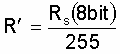
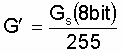
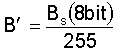
Step 1: scale change (0 to 255) converted to (0 to 1)
The 8 bit integer sRGB code values are converted to floating point R' G' B' values as follows
|
|
|
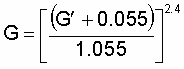
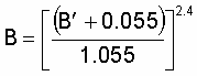
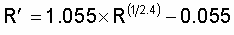
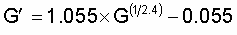
Step 2: adjust for the non-linear output of the display system
The relative amounts of light emitted by the display is determined as follows:
|
If R', G', B' ≤ 0.04045 then |
|
|
|
|
|
If R', G', B' ≥ 0.04045 then |
|
|
|
|
Step 3: Transform the relative light intensities to CIE XYZ values
The relative amounts of light are converted to CIE XYZ values by:
|
|
|
|
|
|
|
|
|
For the purpose of the calculation the value of Y0, the relative luminance of the display at the white point, is normally taken as 100.0
Converting CIE XYZ to sRGB
Step 1: Transform the CIE XYZ values to relative light intensities
The sRGB definitions of the CIE chromaticities of the red, green and blue light emitted by the display result in the following relationships:
|
|
|
|
|
|
|
|
|
Any value of R G or B that is greater than 1.0 or less than 0.0 are clipped to 1.0 and 0.0 respectively.
For the purpose of the calculation the value of Y0, the relative luminance of the white point, is normally taken as 100.0.
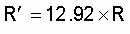
Step 2: Take into account the non-linear output to determine signal sent to the display
The linear values are transformed as follows:
|
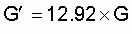
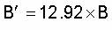
If R, G, or B ≤ 0.0031308 then |
|
|
|
|
|
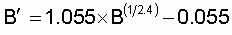
If R, G, or B > 0.0031308 then |
|
|
|
|
|
|
|
|
|
|
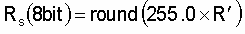
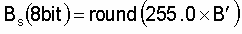
Step 3: Scale change from (0 to 1) to digital codes in the range (0 to 255)
The values are then converted into 8 bit integers, the sRGB values, by:
|
|
|
|
|
|
|
|
|
|
|
|
|
H34: Putting Numbers to Colour: sRGB |
© James H Nobbs |